Assembly Tips#
The most important tip#
So, you got yourself a CNC machine. You open the box, skim the instruction manual, and start putting it together. Not so fast…
A CNC machine has a lot of moving parts. Some of them very sharp!
You will save yourself a lot of headaches if you take the time to examine and test every component before you put them all together.
Troubleshooting a single part is much easier than an entire complex machine.
Go slow, be methodical, have fun.
Examine and test each axis by itself#
This topic applies mostly to machines with ballscrews and linear rails
The machine likely contains 3 or 4 separate axis assemblies - one for X and Z, and one or two for Y. Now is the best time to see if they work smoothly. When they are put together at the factory, little concern is paid to aligning the parts for best performance.
The main thing to check is to ensure that each carriage glides smoothly from end to end without binding. Binding can cause lost steps, premature wear of the motors, and other unpleasantness.
This works best if the motors are not connected to the ballscrews to eliminate the resistance from the motors and allow the ballscrews to spin freely.
If the motors are already pre-installed, you may want to disconnect them.
Turn the ballscrew by hand to move the carriage back and forth the entire length of the axis. Watch for spots where it takes more effort to turn. Such spots indicate that the parts are not well aligned.
I 3D-printed a crank to help me spin the screw by hand.
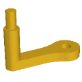
Download in STL format: ballscrew_crank.stl
Download in STEP format: ballscrew_crank.step
The “handle” is made from an M8 bolt, two nuts and two washers.
Here’s my procedure for alignment:
-
Loosen all bolts. This includes:
- (A) Bolts that connect the carriage to the linear blocks
- (B) Bolts that connect the carriage to the ballscrew block (in the picture they are hidden behind the spindle clamp)
- (C) Bolts that connect the ballscrew block to the ballscrew nut
- (D) Bolts that hold the bearing blocks on both ends of the axis, then screw them back until they are snug but not tight
-
Move the carriage to the middle of the axis. Tighten the carriage to the linear blocks (A). Move it end to end a few times. If the axis has 2 linear rails, there may be binding closer to the ends. It would indicate that the rails are not exactly parallel.
- You will have to loosen the bolts on one of the rails
- Move the carriage to one end and tighten the closest 1 or 2 bolts of the rail
- Repeat the process on the other end
- Finish tightening the rail and retest the axis
-
Move the carriage to the middle. Tighten the carriage to the ballscrew block (B). Then tighten the block to the ballscrew nut (C). Move it end to end a few times.
-
Move the carriage to one end and secure the bearing block at that end (D). Repeat for the other end.
If this procedure is not enough to get the axis to smoothly move, here are a few advanced tips
-
Completely disconnect the ballscrew nut from its block and flip it 180 degrees. It could be a bit asymmetric, and it may be just enough to improve things. Or could make it worse. Pick the side that works better
-
If everything moves smoothly with the bolts loosened, but gets worse as you tighten, then you may have to add shims to compensate for the misalignment
-
Completely remove the carriage and test the linear blocks and the ballscrew individually. They may be defective, or lack lubrication
Bonus tip: Ballscrew nuts have an opening for greasing. Chips can get in if the hole is not plugged. Screw in a grease fitting or at least a small grub screw to keep it clean. Take care not to drive the screw too far and damage the ballscrew itself.
Test the motors#
If you have the motors disconnected from the axis assemblies, now is also the best time to test that they work on their own.
Place them on a bench and connect them to the control box with the necessary cables. Turn on the main power.
Connect to a sender software on the PC. More on that here: Connect to a sender software
Likely the software will start in Alarm mode. Dismiss it with the Unlock button. Then jog each axis forward and backward a short distance.
Note: It is possible that the axis will initially only allow movement in one direction. This can happen if the software thinks the axis is at the end of its travel range.
However if you manage to move in one direction, you should be able to then move in the opposite direction.
Things to look for:
- Does the correct motor spin?
- Does the motor spin both ways?
- If you have two motors Y1 and Y2 for the Y axis, do they rotate an equal amount?
- For ballscrew drives Y1 and Y2 should spin in the same direction
- For belt drives they should spin in opposite directions
The main goal is to confirm that the motors are working and that the control box can command them.
If there are issues, you should address them at this stage before you’ve assembled everything.
Read more about motor troubleshooting: Motor troubleshooting
Note: It is not uncommon for the X, Y and Z motors to turn a different amount for the same jog distance. It’s because they will be driving different mechanisms.
Square the frame#
After you assemble the main frame, make sure the frame is square. Use a known good square to test the corners and measure that the two diagonals are the same.
This step is important, but not super critical to get exact at this stage. For machines with separate left and right Y axis, a small inaccuracy can be corrected during tramming. If you have a single Y axis, it is even less critical. It is way more important that the two sides are parallel.
To loctite or not to loctite#
Many people recommend putting Loctite on all screws.

My opinion is to use it sparingly during the initial assembly, only on screws that will be inaccessible later. Then, after you are done with the final assembly and do the initial tramming, you can take the screws out one at a time to add Loctite. I have two reasons for this
- Especially if this is your first time putting a machine together, you may make mistakes and you’ll have to disassemble parts later
- You will have to loosen bolts later during tramming