Wiring a VFD for a Spindle#
How I connected a Huanyang VFD to a FoxAlien Vasto CNC
Introduction#
The 400W spindle that comes with the FoxAlien CNC machines is adequate for a beginner, but for more serious work you need an upgrade. I chose to go with an 800W water-cooled VFD spindle. You get multiple benefits:
- The extra power allows you to cut faster and deeper
- Improved accuracy and stability reduces tool chatter
- You can control the RPMs directly from the G-code
- The spindle is significantly quieter, especially if you choose a water-cooled variant
Here I’ll describe in detail how I achieved this upgrade. My experience is with the Vasto V1 model, however it should work for any other CNC that has a PWM output for a laser module.
There are multiple VFDs and spindles you can buy. I personally decided to go with the Huanyang brand, which had the most comprehensive documentation, and my experience with their warranty support was excellent. The settings and examples here will be for that model.
If you use a different brand, likely the specifics will be different and you will have to consult the documentation that comes with your unit.
This tutorial focuses on the VFD part, and not on the actual spindle wiring. For the spindle you will mainly need a good 4-conductor flexible and shielded cable with a H20-4 aviation male connector. Then simply install the cable inside the drag chain. Many tutorials online cover this part in detail.
VFD overview#
A VFD (Variable Frequency Drive) generates a 3-phase sine wave to power the AC motor of a spindle. The motor will spin with the frequency of the wave.
The VFD has two control inputs that we care about. One is the VI pin, which takes a DC voltage from 0 to 10V and determines the output frequency. The other is the FOR pin, which starts the spindle in the forward direction.
The FoxAlien control boxes don’t provide a DC voltage for setting the spindle speed. What they have instead is a PWM (Pulse-Width Modulation) output for controlling the power of a laser module. Here we use a PWM to DC converter to bridge the two devices.
A common way to connect the FOR pin is to have it permanently enabled. As long as the VI voltage doesn’t go above 0, the spindle will stay still.
I decided that for extra safety I will add a relay to activate the FOR pin using the spindle output from the control box. This is not strictly necessary.
You can simplify the implementation if you omit the relay. Just skip the parts that mention a relay.
Cable and control box modifications#
I made a 4-wire cable with a GX16-2 male connector and a 3 pin JST-XH connector on one end, and a GX12-4 male connector on the other. The first two connectors hook to the spindle and laser outputs of the control box. The other end goes to the VFD assembly (covered in the next chapter).
The 2 wires from the spindle will control the relay and the 2 wires from the laser will control the speed.
Then I needed to ensure that the spindle voltage matches the relay input requirements at all times. If the voltage doesn’t match the relay, bad things will happen. A higher voltage will burn out the relay. A lower voltage will fail to turn on the spindle, causing the CNC to start moving without spinning, eventually crashing the end mill.
The original spindle speed knob is a voltage divider (a potentiometer) that connects to the Vo ADJ input of the power supply.
You have 3 options:
-
Manually adjust the knob to get the right voltage level, and then try not to touch it. This option requires no modifications to the control box
-
Move the potentiometer inside the box to get it out of reach, or even replace it with a small trim pot with a shorter cable as you only need to adjust it once
-
Short-circuit the left two Vo ADJ pins, which will force the output to the max value of 48V - but then you will need specifically a 48V relay. They are less common than 5V, 9V or 12V relays
I chose the last option and bought a 48V relay.
I also 3D-printed a cap to fill the hole left behind from the removed speed knob. The cap has two parts that attach with a simple wood screw.
Modifications for FoxAlien XE-Pro#
I recently upgraded my FoxAlien Vasto CNC to closed loop motors, which came with a new control box. It is the same box that is used by FoxAlien XE-Pro.
I encountered a problem with it. The new control box would output either Spindle or PWM, but not both at the same time.
Note: This is a problem not just for my project. It also prevents you from connecting a VFD spindle and a smart relay for dust collection at the same time.
Here’s how I solved this:
The PCB has a dual pole switch, where one pole controls the spindle power and the other disconnects the PWM signal. The fix was easy - simply solder a piece of wire on the bottom to bypass the switch.
Now the new PCB behaves like the original Vasto machine. PWM is always on, and the switch toggles the spindle power.
The hardest part was to disconnect all the cables from the PCB because they were covered with red glue to keep them secure for shipping. It’s possible if you are careful and take your time.
VFD Assembly#
The PWM to DC converter needs a power source. Luckily, VFDs usually have the ability to supply power to accessories. If your VFD does not, you will need to include an additional DC power source. Possibly the PWM connector on your control box has some sort of power pin you can use. Generally the power voltage needs to be higher than the voltage it needs to provide. In my case I power it with 24V from the VFD, and it outputs a 0-10V signal, which is ideal.
I 3D-printed a box to house the PWM converter and the 48V relay.
It has a 4-pin aviation connector on the top to connect the cable from the control box.
The relay is mounted on a small prototype board, which serves also as a hub for the wiring.
Note: Don’t forget the mounting nut and washer before you solder the wires to the board.
There is a 5-wire ribbon cable from the VFD to the box. The colors are:
Red: 24V - to power the converter
Orange: DCM - ground for power and digital signals
Yellow: FOR - turns on the spindle
Green: VI - Voltage input for the RPMs
Blue: ACM - ground for the analog signals
The VFD and the electronics are bolted onto a 14.5 x 7.5" piece of half-inch plywood.
The AC wires are connected via terminal blocks for cleaner and safer installation.
The FA and FB terminals of the VFD are connected by an internal relay when the spindle is on. I used that feature to control the water pump for the cooling.
Note: The FA, FB and FC terminals were mislabeled in the Huanyang documentation. In practice FB is the input, FA is the normally-open output, and FC is the normally-closed output. If in doubt, use a multimeter to check which pair gets connected when the spindle is running.
I added a banana plug on the side that is connected to ground. I use it to ground the vacuum hose for the dust collection. This fixed all the electric shocks I was getting from the CNC and reduces the static noise that can lead to CNC errors.
And finally, I added a thin plywood cover over the AC area for protection and safety.
Connecting AC and DC grounds#
I added an extra wire to connect the AC ground to the DC ground. This is represented by a dashed line in the schematic.
It permanently connects the spindle to the CNC ground, which means you don’t need the alligator clip when running a Z probe.
This turned out to be an extremely convenient change.
Update the settings#
VFD settings - Huanyang#
The settings here are specific to the Huanyang VFD. You will have to adjust them for the brand you have
PD001 = 1 - this enables the FOR pin to work
PD002 = 1 - this enables the external speed control. There is a jumper on the VFD that switches between VR and VI - make sure it is in the VI (left) position
PD014 = 3 - spin up time in seconds. The default is way too pessimistic
PD015 = 5 - spin down time
PD052 = 01 - connect FA and FB when the spindle is running
PD070 = 0 - use 0-10V input signal
PD144 = 300 - multiplier to convert from Hz to RPM (purely for display purposes). Use the » button on the front of the VFD to switch between different display modes, like Hz or RPM
P.S. If you are using a different brand of VFD, feel free to post your recommended settings in the comments. I will update the article with the new information.
Grbl settings#
Additionally, you need to change the max spindle RPM in the Grbl settings:
$30 = 24000
This is the value that the controller uses to convert G-code speed to PWM level.
Keep in mind that the PWM signal is not very precise and goes through multiple conversions before becoming a VFD frequency. Those conversions are not very accurate, and also not very linear. You will notice that the actual speed will be different from the G-code commands.
There are few things you can do to improve the accuracy. The PWM module has a trim pot that you can adjust with a tiny screwdriver to set the output voltage. Make sure it is at 10V when the G-code runs the spindle at max speed. You can also set $31 to a value larger than 0 to account for the minimum frequency that the VFD can achieve.
It is best to disconnect the spindle when running these tests. Especially air-cooled spindles don’t like it when they run at low speed as they may overheat. Just use the RPM display.
Alternatively, find a G-code value that produces the speed you want. For example maybe for 12000 actual RPM you need something more like 12670 in your program.
VFD modifications#
I did 2 modifications to the VFD itself.
First, I replaced the fan to reduce the noise as described in this video: https://www.youtube.com/watch?v=Uc7bQ9DBf_g
A more complex version of this mod is to control the fan based on the temperature, though I have not attempted it: https://www.youtube.com/watch?v=x882vvX_L7Y
The second mod was to relocate the VFD control panel to the front of the CNC table using an extension cable. A 3D-printed bracket mounts it at a convenient angle.
Necessary supplies#
The main components#
VFD and spindle package: https://www.amazon.com/dp/B07BBHJMQB
PWM to DC converter: https://www.amazon.com/dp/B07XZ836QF
Note: This particular converter model can accept 3.3V and 5V input, which can be selected by a jumper. However the label on the PCB is “24V” instead of “3.3V”. This is because the same PCB is used for multiple models with different input voltages
Prototype PCB: https://www.amazon.com/dp/B0778G64QZ
GX16-2 male aviation connector: https://www.aliexpress.us/item/3256804459446780.html (or reuse from the existing spindle cable)
GX12-4 aviation connector pair (or any suitable low-voltage 4-pin pair)
3-pin JST-XH male connector
48V relay (other voltage can also be used, see below)
Terminal blocks and connectors: https://www.amazon.com/dp/B09WMMZLQY
Wires, fork terminal connectors, a crimping tool
For modding the VFD#
Quieter fan replacement 50x50x10: https://www.amazon.com/dp/B07C2S1MV4
Control panel extension cable: https://www.amazon.com/dp/B07P5LS33N
3D models#
Here are the STL files for everything in this article:
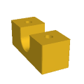
Top half for the speed knob replacement: speed_cap_top.stl
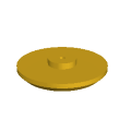
Bottom half for the speed knob replacement: speed_cap_bottom.stl

Top half for the speed knob replacement (XE-Pro version): speed_cap_top_xe.stl

Base for the PWM converter: pwm_base.stl
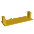
Cover for the PWM converter: pwm_cover.stl

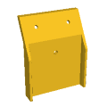
Cover for the GX12 connector: connector_panel.stl

Clip to hold the ribbon cable to the VFD box: ribbon_clip.stl

Clip for the main AC power cable: power_cable_clip.stl

Clip for the spindle cable: spindle_cable_clip.stl
Clip for the water pump cable: pump_cable_clip.stl
Bracket for the banana clip: banana_clip.stl

Bracket for the remote VFD panel: vfd_control_bracket.stl